10 t – 20 t – 30 t
Explanation:
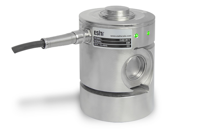
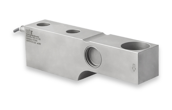
The CAD model has dual sockets, and the connection of the cables is done by connecting in series from one sensor to another. This eliminates the need for a junction box and facilitates replacement in case of failure.
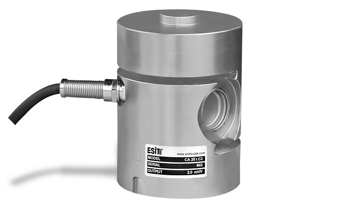
The strain gauge CAD works on the shear force principle to measure loads in the compression direction. It has been developed for high capacity electronic weight and force measurement applications in an industrial environment. Thanks to its strong and precisely made construction, it offers high resistance to lateral forces and overloading.
The stainless steel housing is corrosion resistant, making the CAD sensor suitable for harsh industrial conditions and chemical environments. It finds application in:
High capacity vehicle scales
Platform scales
Tank weighing systems
Process measurements
The main advantage of the CAD model compared to other digital strain gauges is the built-in electronic angle measuring device. Thanks to this feature, the technician receives an indication through colored LED lights for correct installation during installation.
The main problem with automotive scales is lateral forces. The expansion of the platform due to temperature differences between the summer and winter seasons, as well as its deformation due to the distribution of the load, lead to errors in the measurements. In these cases, strain gauges placed perpendicular to the ground can tilt and cause deflections. Thanks to patented angle compensation technology, the vertical angle of deviation is detected by sensors, ensuring accurate weight measurement.
The CAD strain gauge is 80% more resistant to lateral forces compared to other column strain gauges.
Features:
• Certified to OIML R60 standards
• Hermetically sealed housing by welding
• 100% lateral force resistance
• 300% overload resistance
• IP68 industrial protection
• Lightning protection
• Mounting angle compensation
• RS485 communication
• Automatic angle calibration from the indicator
• Detection of measurement errors
• 24-bit A/D converter